This schematic diagram shows the auxiliary heater's coolant hose routing on the Golf/Golf Estate — cross-referenced to repair group 19 for the full coolant circuit and topping-up procedure.
 Note Note
| The schematic diagram for the entire coolant circuit can be
found in the repair group 19
→ Rep. gr.19. |
| Topping up coolant and bleeding coolant circuit
→ Rep. gr.19 and
→ Chapter |
|
|
|
Note
| The -arrows- indicate the direction of
coolant flow. |
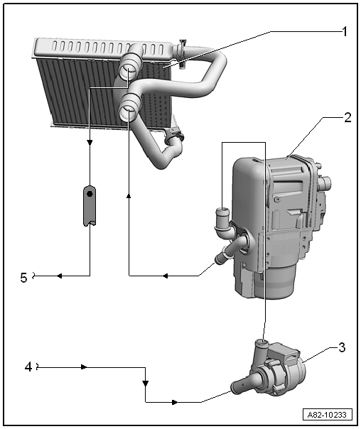
| 1 - |
Heat exchanger for heater in heater and air conditioning unit |
| Incorporation in coolant circuit
→ Rep. gr.19. |
| Removing and installing
→ Chapter. |
| 3 - |
Circulation pump -V55- |
| The circulation pump -V55- is integrated in the hose assembly of the
auxiliary heater. |
| Removing and installing
→ Chapter |
Note
| For this vehicle (only selected engine types), a Start/Stop system
is offered as an optional equipment. |
| On vehicles equipped with a Start/Stop system, the circulation pump
-V55- of the auxiliary heater can be actuated by the auxiliary heater
control unit -J364- while the stop function is active. To achieve this,
the auxiliary heater control unit -J364- receives a command from the air
conditioning system operating unit, the Climatronic control unit -J255-
and the air conditioning system control unit -J301- via the data bus to
switch on the circulation pump -V55-; vehicle diagnostic tester in
“Guided fault finding” mode. |
| 4 - |
Coolant supply from engine |
| Incorporation of auxiliary/supplementary heater in engine coolant
circuit
→ Rep. gr.19. |
| 5 - |
Coolant return to the engine |
| Incorporation of auxiliary/supplementary heater in engine coolant
circuit
→ Rep. gr.19. |
Questions & answers
Schematic diagram - coolant hoses, Golf and Golf Estate — Volkswagen Golf Mk7
Where can I find the full Golf Mk7 coolant circuit diagram?
The complete coolant circuit schematic is in repair group 19. The auxiliary heater chapter shows only the heater-specific portion.
Note
Currently, only the auxiliary heater function is available.
At the moment the auxiliary heater is not intended to be
operated as a supplemen ...


